Embarking on a robotics project can be both exciting and educational, especially when you’re building something tangible like a line-following robot. Utilizing an Arduino, one of the most popular microcontrollers, makes the process accessible even for beginners. In this guide, we’ll walk you through the steps to create a simple line-following robot that can navigate a path autonomously.
Materials You’ll Need
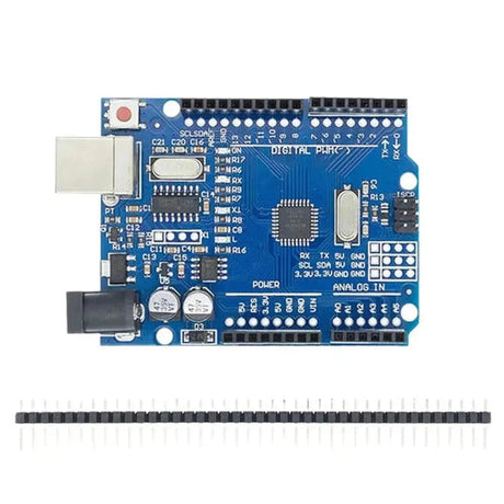
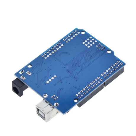
- Arduino Uno – The brain of your robot.
- Motor Driver Module (L298N) – To control the motors.
- DC Motors with Wheels – For movement.
- Chassis – The frame to hold all components.
- Line Sensor Module (e.g., QRE1113) – To detect the line.
- Battery Pack – Power source for the robot.
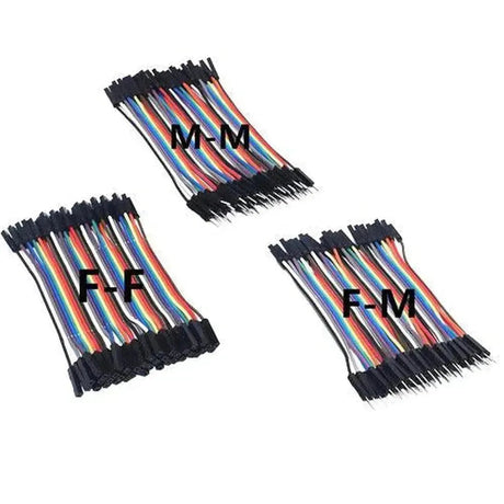
- Jumper Wires – For connections.
- Breadboard – For prototyping connections.
- Screws, Nuts, and Bolts – To assemble the chassis.
Step 1: Assembling the Chassis
The chassis serves as the foundation of your robot. Start by attaching the DC motors to the chassis using screws and nuts. Ensure that the motors are securely fixed to prevent any movement during operation. Attach the wheels to the motor shafts and position the battery pack and Arduino onto the chassis. Make sure all components fit well and are within easy reach for wiring.
Step 2: Wiring the Motors
Connect the DC motors to the motor driver module (L298N). The motor driver acts as an interface between the Arduino and the motors, allowing the Arduino to control motor speed and direction without being overloaded.
// Connect motor A
const int motorA_EN = 9;
const int motorA_IN1 = 7;
const int motorA_IN2 = 8;

// Connect motor B
const int motorB_EN = 10;
const int motorB_IN3 = 5;
const int motorB_IN4 = 6;

void setup() {
  // Motor A
  pinMode(motorA_EN, OUTPUT);
  pinMode(motorA_IN1, OUTPUT);
  pinMode(motorA_IN2, OUTPUT);

  // Motor B
  pinMode(motorB_EN, OUTPUT);
  pinMode(motorB_IN3, OUTPUT);
  pinMode(motorB_IN4, OUTPUT);
}
Step 3: Connecting the Line Sensor
The line sensor detects the contrast between the line and the surface. Typically, these sensors have infrared LEDs and photodiodes to detect reflecting surfaces. Connect the sensor’s VCC and GND to the Arduino’s 5V and GND respectively. The sensor’s output pins will be connected to the Arduino’s digital or analog pins based on the sensor type.
// Line sensor pins
const int sensorLeft = A0;
const int sensorRight = A1;

void setup() {
  pinMode(sensorLeft, INPUT);
  pinMode(sensorRight, INPUT);
}
Step 4: Writing the Arduino Code
The Arduino code will read the sensor values and control the motors accordingly to follow the line. Below is a simple example of how the code might look:
// Define motor pins
const int motorA_EN = 9;
const int motorA_IN1 = 7;
const int motorA_IN2 = 8;
const int motorB_EN = 10;
const int motorB_IN3 = 5;
const int motorB_IN4 = 6;

// Define sensor pins
const int sensorLeft = A0;
const int sensorRight = A1;

// Threshold for line detection
const int threshold = 500;

void setup() {
  // Initialize motor pins
  pinMode(motorA_EN, OUTPUT);
  pinMode(motorA_IN1, OUTPUT);
  pinMode(motorA_IN2, OUTPUT);

  pinMode(motorB_EN, OUTPUT);
  pinMode(motorB_IN3, OUTPUT);
  pinMode(motorB_IN4, OUTPUT);

  // Initialize sensor pins
  pinMode(sensorLeft, INPUT);
  pinMode(sensorRight, INPUT);

  // Start serial communication for debugging
  Serial.begin(9600);
}

void loop() {
  int leftSensor = analogRead(sensorLeft);
  int rightSensor = analogRead(sensorRight);

  Serial.print("Left: ");
  Serial.print(leftSensor);
  Serial.print(" | Right: ");
  Serial.println(rightSensor);

  if (leftSensor > threshold && rightSensor > threshold) {
    // Move forward
    moveForward();
  }
  else if (leftSensor < threshold && rightSensor > threshold) {
    // Turn right
    turnRight();
  }
  else if (leftSensor > threshold && rightSensor < threshold) {
    // Turn left
    turnLeft();
  }
  else {
    // Stop
    stopMovement();
  }
}

void moveForward() {
  digitalWrite(motorA_IN1, HIGH);
  digitalWrite(motorA_IN2, LOW);
  digitalWrite(motorB_IN3, HIGH);
  digitalWrite(motorB_IN4, LOW);

  analogWrite(motorA_EN, 200);
  analogWrite(motorB_EN, 200);
}

void turnRight() {
  digitalWrite(motorA_IN1, HIGH);
  digitalWrite(motorA_IN2, LOW);
  digitalWrite(motorB_IN3, LOW);
  digitalWrite(motorB_IN4, LOW);

  analogWrite(motorA_EN, 200);
  analogWrite(motorB_EN, 0);
}

void turnLeft() {
  digitalWrite(motorA_IN1, LOW);
  digitalWrite(motorA_IN2, LOW);
  digitalWrite(motorB_IN3, HIGH);
  digitalWrite(motorB_IN4, LOW);

  analogWrite(motorA_EN, 0);
  analogWrite(motorB_EN, 200);
}

void stopMovement() {
  digitalWrite(motorA_IN1, LOW);
  digitalWrite(motorA_IN2, LOW);
  digitalWrite(motorB_IN3, LOW);
  digitalWrite(motorB_IN4, LOW);

  analogWrite(motorA_EN, 0);
  analogWrite(motorB_EN, 0);
}
Step 5: Powering Up the Robot
Once all connections are made, connect your battery pack to the Arduino and the motor driver. Ensure that the polarity is correct to prevent any damage to the components. It’s a good practice to test the connections with a multimeter before powering up.
Testing and Calibration
After powering up, place your robot on a surface with a clear line (e.g., black tape on white paper). Observe how it behaves and make necessary adjustments. You might need to tweak the sensor threshold or adjust the speed by changing the PWM values in the code to achieve optimal performance.
Tips for Success
- Ensure Stable Connections: Loose wires can cause intermittent behavior. Use a breadboard for prototyping and consider soldering connections for a permanent setup.
- Use Quality Sensors: Reliable line sensors can significantly improve your robot’s performance.
- Calibrate Your Sensors: Different surfaces and lighting conditions can affect sensor readings. Calibrate your thresholds accordingly.
- Optimize Code: Efficient code ensures quick response times. Make sure there are no unnecessary delays in your loop.
Enhancements and Further Learning
Once you’ve successfully built a basic line-following robot, consider adding more features to enhance its capabilities:
- Intersection Detection: Enable your robot to make decisions at junctions.
- Speed Control: Implement dynamic speed adjustments based on sensor input.
- Wireless Control: Add Bluetooth or Wi-Fi modules to control your robot remotely.
- Obstacle Avoidance: Incorporate ultrasonic sensors to navigate around obstacles.
Building a line-following robot with Arduino is a fantastic way to dive into the world of robotics and embedded systems. It teaches you fundamental concepts such as sensor integration, motor control, and real-time decision-making. With patience and experimentation, you can expand this basic project into a more complex and capable robot. Happy building!