
The L9110S motor driver is a compact and efficient solution for controlling DC motors and stepper motors in your Arduino projects. Whether you're building a simple robot or a more complex automation system, the L9110S offers a reliable way to manage motor operations with minimal wiring and programming complexity. In this blog post, we'll explore the features of the L9110S motor driver, how to connect it to an Arduino, and provide sample code to get you started.
What is the L9110S?
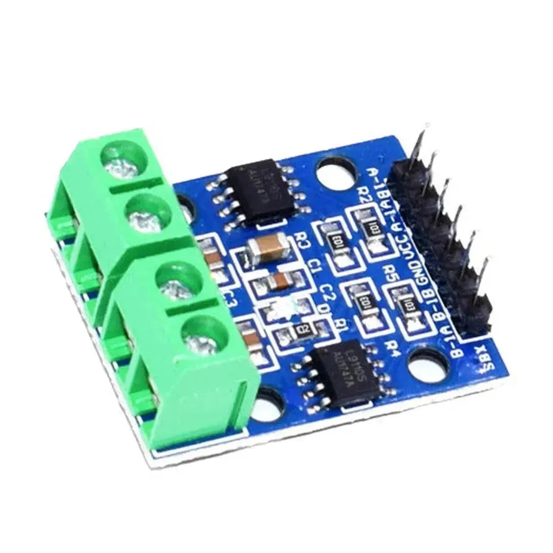
The L9110S is a dual-channel motor driver IC designed to control the speed and direction of two DC motors or one stepper motor. It operates on a voltage range of 2.5V to 12V, making it versatile for various applications. The L9110S is known for its compact size, low power consumption, and ease of integration with microcontrollers like the Arduino.
Why Choose the L9110S?
- Compact Design: Its small footprint makes it ideal for projects with limited space.
- Dual Channels: Control two motors independently, allowing for complex movements.
- Easy to Use: Simple interface with clear labeling for easy connections.
- Cost-Effective: Affordable pricing without compromising on functionality.
Connecting the L9110S to Arduino
Setting up the L9110S with an Arduino is straightforward. Below is a step-by-step guide to making the connections:
- Power Connections:
- Connect the
VCCpin of the L9110S to the 5V pin on the Arduino. - Connect the
GNDpin of the L9110S to the GND pin on the Arduino. - Motor Connections:
- Connect the first motor to the
OUT1andOUT2pins. - If using a second motor, connect it to the
OUT3andOUT4pins. -
Control Pins:
- Connect the
AIN1andAIN2pins to two digital pins on the Arduino (e.g., pins 2 and 3). - If using a second motor, connect
BIN1andBIN2to two other digital pins (e.g., pins 4 and 5).
- Connect the
Refer to the diagram below for a visual representation of the connections:
Programming the Arduino
After setting up the hardware, the next step is to program the Arduino to control the motors. Below is a sample code that demonstrates how to control the direction and speed of a DC motor using the L9110S motor driver.
// Define motor control pins
const int AIN1 = 2;
const int AIN2 = 3;

// Setup function
void setup() {
  // Initialize the motor control pins as outputs
  pinMode(AIN1, OUTPUT);
  pinMode(AIN2, OUTPUT);
}

// Loop function
void loop() {
  // Rotate motor forward
  digitalWrite(AIN1, HIGH);
  digitalWrite(AIN2, LOW);
  delay(2000); // Run for 2 seconds

  // Stop the motor
  digitalWrite(AIN1, LOW);
  digitalWrite(AIN2, LOW);
  delay(1000); // Stop for 1 second

  // Rotate motor backward
  digitalWrite(AIN1, LOW);
  digitalWrite(AIN2, HIGH);
  delay(2000); // Run for 2 seconds

  // Stop the motor
  digitalWrite(AIN1, LOW);
  digitalWrite(AIN2, LOW);
  delay(1000); // Stop for 1 second
}
Explanation:
-
AIN1andAIN2are used to control the direction of the motor. - Setting
AIN1HIGH andAIN2LOW rotates the motor forward. - Setting
AIN1LOW andAIN2HIGH rotates the motor backward. - Setting both
AIN1andAIN2LOW stops the motor.
Controlling Speed with PWM
The L9110S supports PWM (Pulse Width Modulation) for speed control. By varying the PWM signal's duty cycle, you can adjust the motor's speed. Here's how to modify the previous code to include speed control:
// Define motor control pins
const int AIN1 = 2;
const int AIN2 = 3;
const int PWM_PIN = 9; // PWM pin for speed control

// Setup function
void setup() {
  // Initialize the motor control pins as outputs
  pinMode(AIN1, OUTPUT);
  pinMode(AIN2, OUTPUT);
  pinMode(PWM_PIN, OUTPUT);
}

// Loop function
void loop() {
  // Set speed to 150 out of 255
  analogWrite(PWM_PIN, 150);

  // Rotate motor forward
  digitalWrite(AIN1, HIGH);
  digitalWrite(AIN2, LOW);
  delay(2000); // Run for 2 seconds

  // Stop the motor
  digitalWrite(AIN1, LOW);
  digitalWrite(AIN2, LOW);
  delay(1000); // Stop for 1 second

  // Rotate motor backward
  digitalWrite(AIN1, LOW);
  digitalWrite(AIN2, HIGH);
  delay(2000); // Run for 2 seconds

  // Stop the motor
  digitalWrite(AIN1, LOW);
  digitalWrite(AIN2, LOW);
  delay(1000); // Stop for 1 second
}
Explanation: The analogWrite() function sends a PWM signal to the motor, allowing you to control its speed. The value ranges from 0 (stop) to 255 (full speed).
Applications of L9110S with Arduino
The combination of the L9110S motor driver and Arduino opens up a wide range of project possibilities:
- Robotics: Control the movement of robotic arms or mobile robots with precise motor control.
- Automation Systems: Automate tasks such as opening/closing doors, adjusting valves, or moving components in assembly lines.
- DIY Projects: Create custom electronics projects like motorized camera sliders, automated plant watering systems, or remote-controlled vehicles.
- Educational Tools: Teach students about motor control, electronics, and programming through hands-on projects.
Conclusion
The L9110S motor driver is a versatile and user-friendly component for anyone looking to control motors using an Arduino. Its dual-channel capability, combined with simplicity in wiring and programming, makes it an excellent choice for both beginners and experienced hobbyists. By following the steps outlined in this post, you can quickly integrate motor control into your projects and expand the functionality of your Arduino-based systems.
Experiment with different motor speeds, directions, and applications to fully harness the potential of the L9110S motor driver. Happy tinkering!