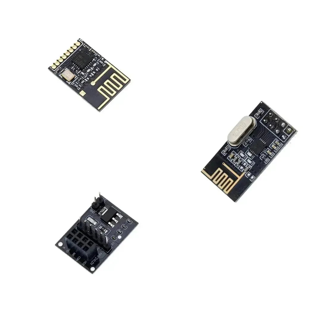

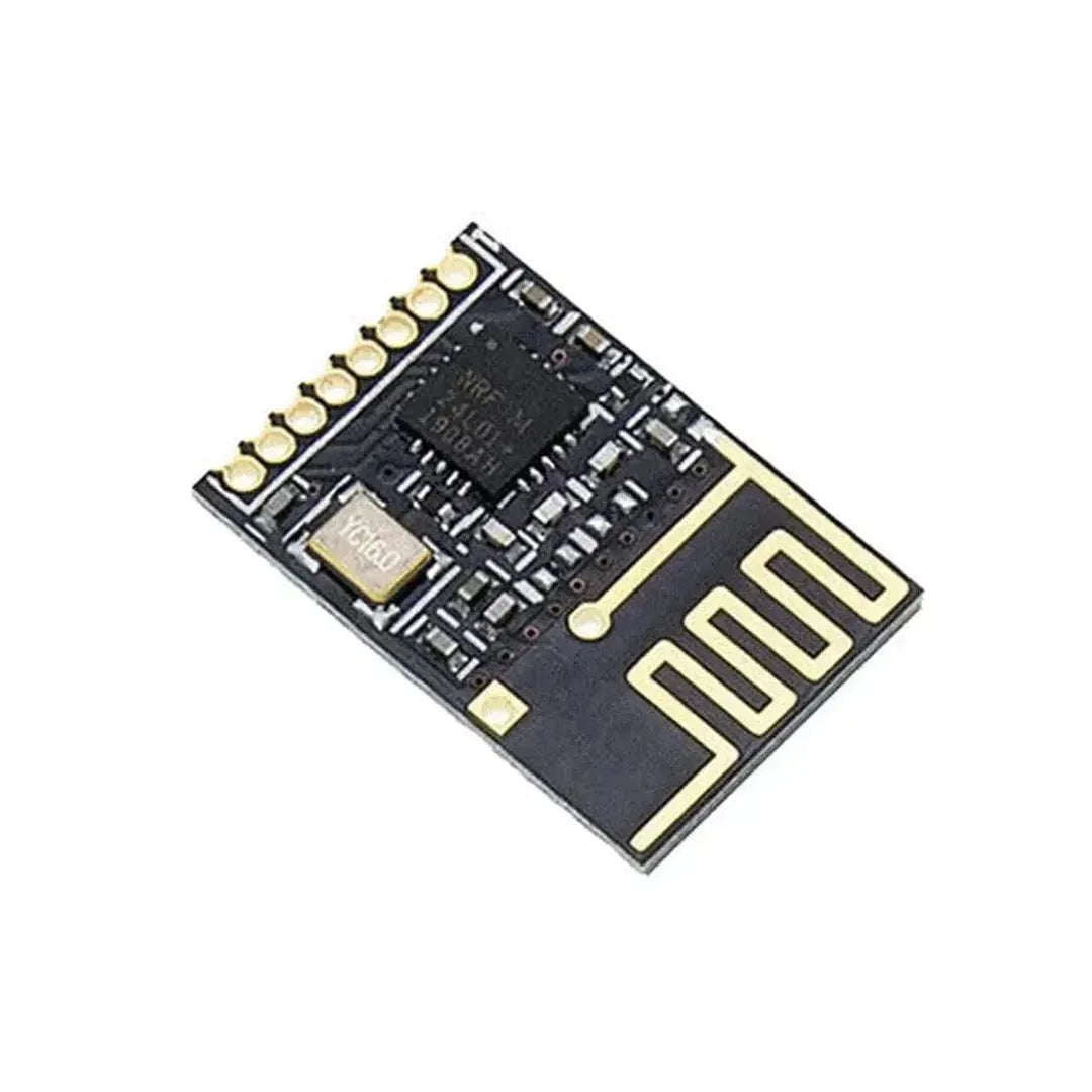

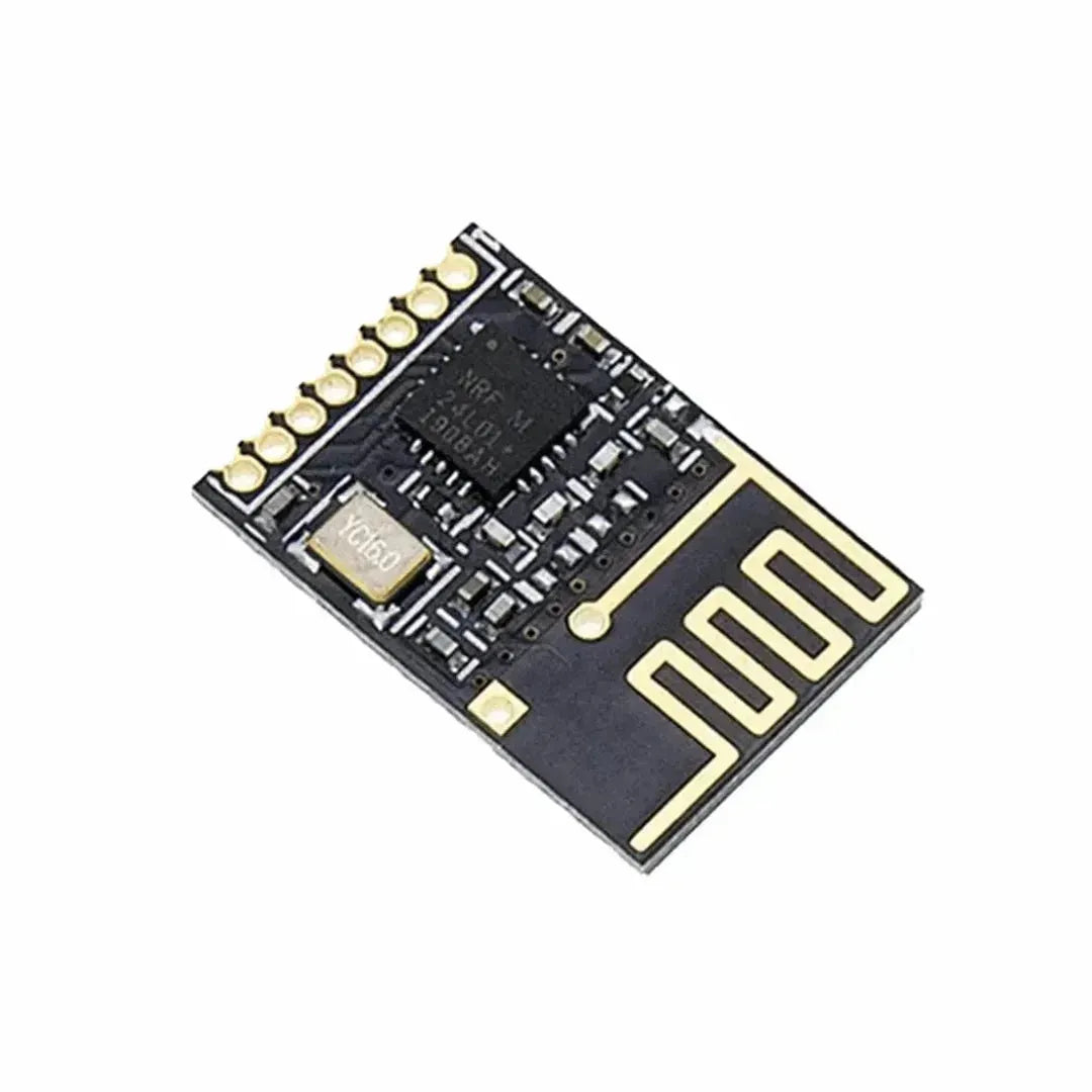
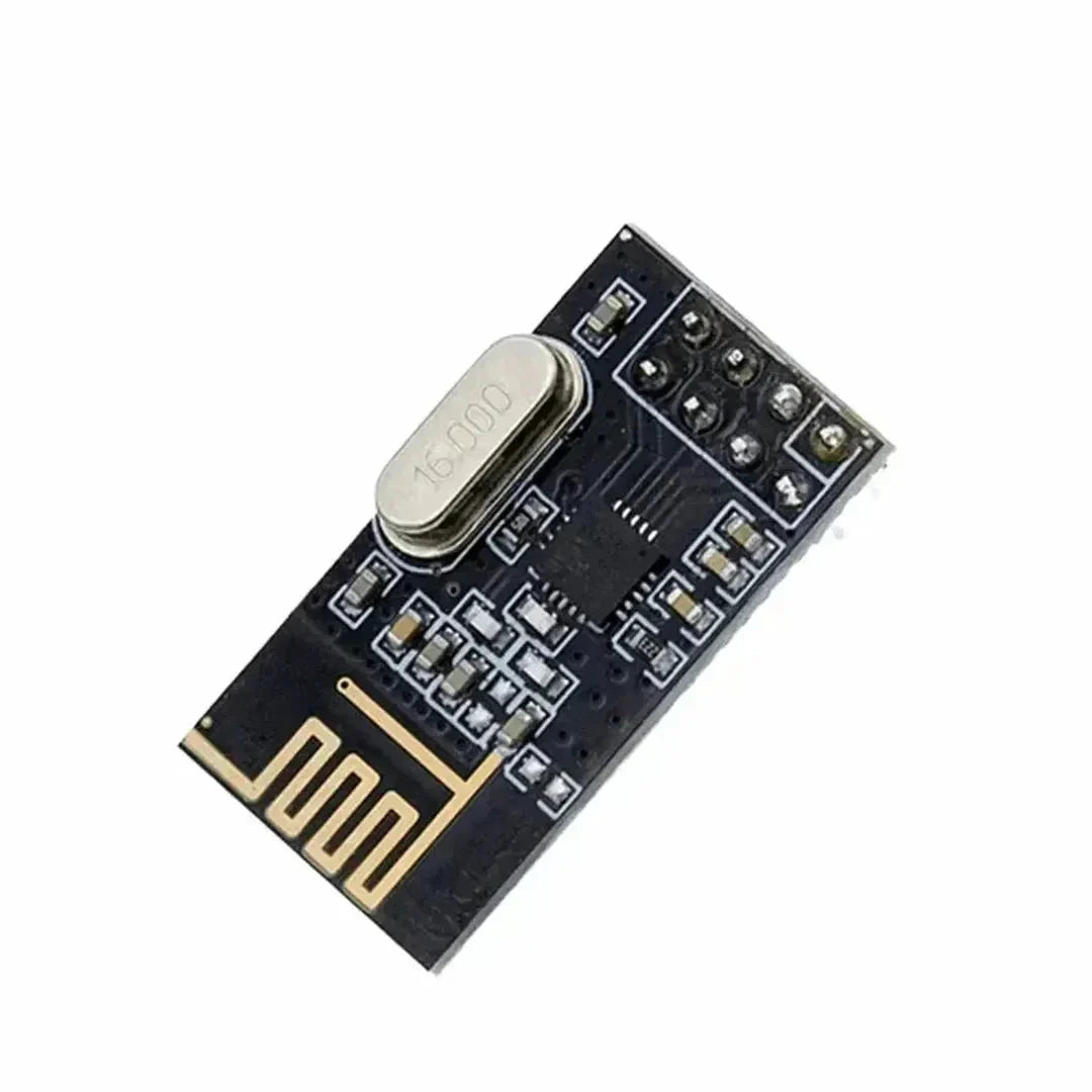
Wireless communication is a cornerstone of modern electronics, enabling devices to communicate without the constraint of wires. One popular module for achieving this with Arduino is the NRF24L01. This versatile, low-cost 2.4GHz wireless transceiver module is perfect for projects requiring reliable data transmission over short distances. In this guide, we'll walk you through the steps to set up and use the NRF24L01 with your Arduino.
Components You’ll Need
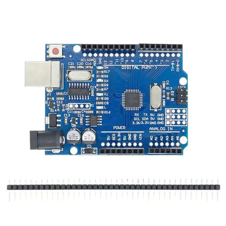
- 2x Arduino boards (e.g., Arduino Uno)
- 2x NRF24L01 modules
- Jumper wires
- Breadboard (optional)
- 10µF capacitor (recommended)
Wiring the NRF24L01 to Arduino
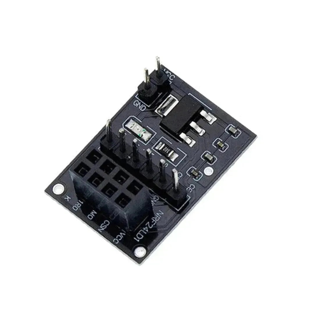
Connecting the NRF24L01 to your Arduino requires attention to detail. Here's a simple wiring diagram:
If you don’t have a wiring diagram, follow these connections:
- NRF24L01 VCC to Arduino 3.3V
- NRF24L01 GND to Arduino GND
- NRF24L01 CE to Arduino pin 9
- NRF24L01 CSN to Arduino pin 10
- NRF24L01 SCK to Arduino pin 13
- NRF24L01 MOSI to Arduino pin 11
- NRF24L01 MISO to Arduino pin 12
Note: It's recommended to add a 10µF capacitor between VCC and GND of the NRF24L01 to stabilize the power supply.
Installing the Required Libraries
To simplify communication with the NRF24L01, we'll use the RF24 library. Follow these steps to install it:
- Open the Arduino IDE.
- Navigate to Sketch > Include Library > Manage Libraries...
- Search for RF24 by TMRh20.
- Click Install.
Writing the Arduino Code
We'll create two sketches: one for the transmitter and one for the receiver.
Transmitter Code
    #include <SPI.h>
    #include <RF24.h>

    // CE and CSN pins
    RF24 radio(9, 10);

    // Address for communication
    const byte address[6] = "00001";

    void setup() {
        Serial.begin(9600);
        radio.begin();
        radio.openWritingPipe(address);
        radio.setPALevel(RF24_PA_MIN);
    }

    void loop() {
        const char text[] = "Hello World";
        bool report = radio.write(&text, sizeof(text));
        if (report) {
            Serial.println("Data sent successfully");
        } else {
            Serial.println("Transmission failed");
        }
        delay(1000);
    }
Receiver Code
    #include <SPI.h>
    #include <RF24.h>

    // CE and CSN pins
    RF24 radio(9, 10);

    // Address for communication
    const byte address[6] = "00001";

    void setup() {
        Serial.begin(9600);
        radio.begin();
        radio.openReadingPipe(0, address);
        radio.setPALevel(RF24_PA_MIN);
        radio.startListening();
    }

    void loop() {
        if (radio.available()) {
            char text[32] = "";
            radio.read(&text, sizeof(text));
            Serial.println(text);
        }
    }
Uploading the Code
Upload the transmitter code to the first Arduino and the receiver code to the second Arduino. Once both are running, open the Serial Monitor for the receiver Arduino at 9600 baud rate. You should see the message "Hello World" being received every second.
Troubleshooting Tips
- Power Issues: Ensure that both NRF24L01 modules receive a stable 3.3V supply. Using a capacitor can help prevent power fluctuations.
- Wiring Accuracy: Double-check all connections to avoid miswiring, which can prevent communication.
-
Library Compatibility: Ensure that the
RF24library is correctly installed and updated. - Address Matching: Make sure both transmitter and receiver use the same communication address.
Conclusion
The NRF24L01 module is a powerful tool for adding wireless capabilities to your Arduino projects. By following the steps outlined above, you can set up a reliable communication link between two Arduino boards. Whether you're building a remote sensor network, a wireless control system, or experimenting with IoT applications, the NRF24L01 offers a versatile and cost-effective solution.