Serial Peripheral Interface (SPI) is a synchronous serial communication protocol widely used for short-distance communication, primarily in embedded systems. Combining the versatility of the Arduino with the computational power of the Raspberry Pi through SPI can open up a plethora of project possibilities. In this blog post, we'll explore how to set up and use SPI communication between an Arduino and a Raspberry Pi.
Understanding SPI
SPI is a full-duplex communication protocol that operates in master-slave mode. It uses four main lines:
- MOSI (Master Out Slave In): Transfers data from master to slave.
- MISO (Master In Slave Out): Transfers data from slave to master.
- SCLK (Serial Clock): Synchronizes data transmission generated by the master.
- SS/CS (Slave Select/Chip Select): Selects the slave device.
SPI is favored for its simplicity and speed, making it ideal for applications requiring quick data exchange between devices.
Why Use SPI with Arduino and Raspberry Pi?
Combining an Arduino with a Raspberry Pi leverages the strengths of both platforms. The Arduino excels at real-time, low-level hardware control, while the Raspberry Pi offers high-level processing capabilities, network connectivity, and a rich operating system environment. Using SPI allows these two devices to communicate efficiently, enabling complex projects like home automation systems, robotics, and data logging applications.
Setting Up the Hardware
To establish SPI communication between an Arduino and a Raspberry Pi, you'll need the following components:
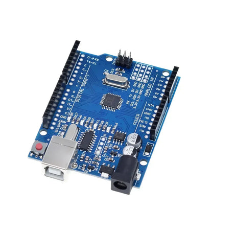
- Arduino Uno (or any compatible Arduino board)
- Raspberry Pi (any model with GPIO pins)
- Jumper wires
- Breadboard (optional)
Wiring the Arduino and Raspberry Pi for SPI
Careful wiring is crucial to ensure proper communication. Here's how to connect the Arduino and Raspberry Pi using SPI:
| Raspberry Pi GPIO Pin | Arduino Pin | Description |
|---|---|---|
| GPIO10 (MOSI) | Pin 11 (MOSI) | Master Out Slave In |
| GPIO9 (MISO) | Pin 12 (MISO) | Master In Slave Out |
| GPIO11 (SCLK) | Pin 13 (SCLK) | Serial Clock |
| GPIO8 (CE0) | Pin 10 (SS) | Slave Select |
| GND | GND | Common Ground |
| 3.3V | 5V | Power Supply (Use level shifting if necessary) |
Note: The Raspberry Pi operates at 3.3V logic levels, while Arduino Uno uses 5V. It is recommended to use a logic level converter to prevent potential damage to the Raspberry Pi.
Configuring the Arduino
The Arduino will act as the SPI slave device. Below is a sample Arduino sketch to set it up:
// Arduino as SPI Slave

#include

volatile byte receivedData = 0;

void setup() {
  // Initialize serial communication for debugging
  Serial.begin(9600);

  // Set MISO as output
  pinMode(MISO, OUTPUT);

  // Enable SPI in Slave Mode
  SPCR |= _BV(SPE);
  SPI.attachInterrupt();
}

ISR(SPI_STC_vect) {
  receivedData = SPDR;
}

void loop() {
  if (receivedData) {
    Serial.print("Received: ");
    Serial.println(receivedData);
    receivedData = 0;
  }
}
Explanation:
- SPI.attachInterrupt(); enables the SPI interrupt, allowing the Arduino to handle incoming data.
- In the interrupt service routine
ISR(SPI_STC_vect), the received data is stored for processing. - The
loop()function checks for received data and prints it to the serial monitor.
Configuring the Raspberry Pi
The Raspberry Pi will act as the SPI master device. We'll use Python with the spidev library to handle SPI communication. First, ensure SPI is enabled:
- Open the Raspberry Pi configuration tool:
sudo raspi-config - Navigate to Interface Options > SPI > Enable
- Reboot the Raspberry Pi if prompted.
Install the spidev library if it's not already installed:
sudo apt-get install python3-spidevHere's a sample Python script for the Raspberry Pi:
# Raspberry Pi as SPI Master

import spidev
import time

# Open SPI bus 0, device (CS) 0
spi = spidev.SpiDev()
spi.open(0, 0)

# Set SPI speed and mode
spi.max_speed_hz = 50000
spi.mode = 0

def send_data(data):
    """Send a single byte to the SPI slave"""
    response = spi.xfer2([data])
    return response

try:
    while True:
        data = 42  # Example data byte
        print(f"Sending: {data}")
        resp = send_data(data)
        print(f"Received: {resp[0]}")
        time.sleep(1)

except KeyboardInterrupt:
    spi.close()
Explanation:
- spi.open(0, 0) opens SPI bus 0, device 0 (CE0).
- spi.xfer2([data]) sends the data byte and simultaneously receives data from the slave.
- The script sends a byte (e.g., 42) every second and prints the response from the Arduino.
Testing the Communication
After setting up both the Arduino and Raspberry Pi:
- Upload the Arduino sketch to the Arduino board.
- Connect the Arduino to the Raspberry Pi via the SPI wiring.
- Run the Python script on the Raspberry Pi:
python3 spi_master.py - Open the Arduino Serial Monitor to view the received data:
Tools > Serial Monitor
You should see the Arduino receiving the data sent by the Raspberry Pi and displaying it in the Serial Monitor. Similarly, the Raspberry Pi will display the data it sends and the response it receives.
Troubleshooting Tips
- Check Wiring: Ensure all connections between the Arduino and Raspberry Pi are secure and correctly mapped.
- Voltage Levels: Use a logic level converter to match the 3.3V of the Raspberry Pi with the 5V of the Arduino.
-
Enable SPI: Verify that SPI is enabled on the Raspberry Pi using
raspi-config. -
Permissions: Ensure your user has the necessary permissions to access SPI devices. You might need to run your Python script with
sudo. - Baud Rate: Make sure the serial monitor and the Arduino sketch are using the same baud rate.
- SPI Settings: Ensure that both the master and slave are configured with the same SPI mode and speed.
Conclusion
Using SPI communication between an Arduino and a Raspberry Pi allows you to harness the strengths of both platforms effectively. Whether you're building a complex robotics system, developing a sensor network, or experimenting with data logging, understanding SPI is invaluable. By following the steps outlined in this guide, you can set up reliable SPI communication and embark on exciting embedded projects that leverage the power of both Arduino and Raspberry Pi.Happy tinkering!