Ang pagsisimula sa isang proyekto ng robotics ay maaaring maging kapana-panabik at pang-edukasyon, lalo na kung nagtatayo ka ng isang bagay na nasasalat tulad ng isang robot na sumusunod sa linya. Utilizing an Arduino, one of the most popular microcontrollers, makes the process accessible even for beginners. In this guide, we’ll walk you through the steps to create a simple line-following robot that can navigate a path autonomously.
Materials You’ll Need
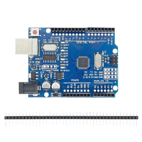
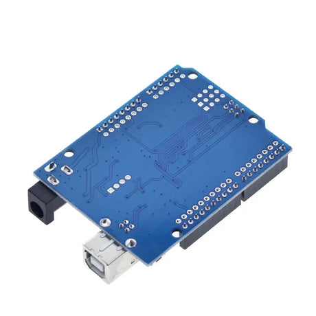
- Arduino Uno – The brain of your robot.
- Module ng driver ng motor (L298N) - Upang makontrol ang mga motor.
- Ang mga motor ng DC na may mga gulong - Para sa paggalaw.
- Tsasis - Ang frame upang hawakan ang lahat ng mga sangkap.
- Linya ng sensor ng linya (hal., QRE1113) - Upang makita ang linya.
- Baterya pack - Pinagmulan ng kapangyarihan para sa robot.
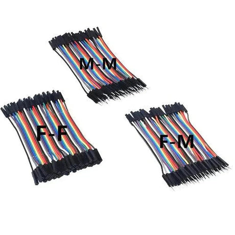
- Jumper wires - Para sa mga koneksyon.
- Tinapay - para sa mga koneksyon sa prototyping.
- Mga screws, nuts, at bolts - Upang tipunin ang tsasis.
Hakbang 1: Pagtitipon ng tsasis
Ang tsasis ay nagsisilbing pundasyon ng iyong robot. Magsimula sa pamamagitan ng paglakip sa mga motor ng DC sa tsasis gamit ang mga turnilyo at mani. Tiyakin na ang mga motor ay ligtas na naayos upang maiwasan ang anumang paggalaw sa panahon ng operasyon. Ikabit ang mga gulong sa mga shaft ng motor at iposisyon ang pack ng baterya at Arduino sa tsasis. Make sure all components fit well and are within easy reach for wiring.
Step 2: Wiring the Motors
Connect the DC motors to the motor driver module (L298N). Ang driver ng motor ay kumikilos bilang isang interface sa pagitan ng Arduino at Motors, na pinapayagan ang Arduino na kontrolin ang bilis ng motor at direksyon nang hindi na -overload.
// Connect motor A
const int motorA_EN = 9;
const int motorA_IN1 = 7;
const int motorA_IN2 = 8;

// Connect motor B
const int motorB_EN = 10;
const int motorB_IN3 = 5;
const int motorB_IN4 = 6;

void setup() {
  // Motor A
  pinMode(motorA_EN, OUTPUT);
  pinMode(motorA_IN1, OUTPUT);
  pinMode(motorA_IN2, OUTPUT);

  // Motor B
  pinMode(motorB_EN, OUTPUT);
  pinMode(motorB_IN3, OUTPUT);
  pinMode(motorB_IN4, OUTPUT);
}
Step 3: Connecting the Line Sensor
The line sensor detects the contrast between the line and the surface. Typically, these sensors have infrared LEDs and photodiodes to detect reflecting surfaces. Ikonekta ang VCC ng sensor at GND sa Arduino's 5V at GND ayon sa pagkakabanggit. Ang mga output ng sensor ng sensor ay konektado sa digital o analog pin ng Arduino batay sa uri ng sensor.
// Line sensor pins
const int sensorLeft = A0;
const int sensorRight = A1;

void setup() {
  pinMode(sensorLeft, INPUT);
  pinMode(sensorRight, INPUT);
}
Hakbang 4: Pagsulat ng Arduino Code
Babasahin ng Arduino Code ang mga halaga ng sensor at kontrolin ang mga motor na naaayon upang sundin ang linya. Nasa ibaba ang isang simpleng halimbawa ng kung paano maaaring tumingin ang code:
// Define motor pins
const int motorA_EN = 9;
const int motorA_IN1 = 7;
const int motorA_IN2 = 8;
const int motorB_EN = 10;
const int motorB_IN3 = 5;
const int motorB_IN4 = 6;

// Define sensor pins
const int sensorLeft = A0;
const int sensorRight = A1;

// Threshold for line detection
const int threshold = 500;

void setup() {
  // Initialize motor pins
  pinMode(motorA_EN, OUTPUT);
  pinMode(motorA_IN1, OUTPUT);
  pinMode(motorA_IN2, OUTPUT);

  pinMode(motorB_EN, OUTPUT);
  pinMode(motorB_IN3, OUTPUT);
  pinMode(motorB_IN4, OUTPUT);

  // Initialize sensor pins
  pinMode(sensorLeft, INPUT);
  pinMode(sensorRight, INPUT);

  // Start serial communication for debugging
  Serial.begin(9600);
}

void loop() {
  int leftSensor = analogRead(sensorLeft);
  int rightSensor = analogRead(sensorRight);

  Serial.print("Left: ");
  Serial.print(leftSensor);
  Serial.print(" | Right: ");
  Serial.println(rightSensor);

  if (leftSensor > threshold && rightSensor > threshold) {
    // Move forward
    moveForward();
  }
  else if (leftSensor < threshold && rightSensor > threshold) {
    // Turn right
    turnRight();
  }
  else if (leftSensor > threshold && rightSensor < threshold) {
    // Turn left
    turnLeft();
  }
  else {
    // Stop
    stopMovement();
  }
}

void moveForward() {
  digitalWrite(motorA_IN1, HIGH);
  digitalWrite(motorA_IN2, LOW);
  digitalWrite(motorB_IN3, HIGH);
  digitalWrite(motorB_IN4, LOW);

  analogWrite(motorA_EN, 200);
  analogWrite(motorB_EN, 200);
}

void turnRight() {
  digitalWrite(motorA_IN1, HIGH);
  digitalWrite(motorA_IN2, LOW);
  digitalWrite(motorB_IN3, LOW);
  digitalWrite(motorB_IN4, LOW);

  analogWrite(motorA_EN, 200);
  analogWrite(motorB_EN, 0);
}

void turnLeft() {
  digitalWrite(motorA_IN1, LOW);
  digitalWrite(motorA_IN2, LOW);
  digitalWrite(motorB_IN3, HIGH);
  digitalWrite(motorB_IN4, LOW);

  analogWrite(motorA_EN, 0);
  analogWrite(motorB_EN, 200);
}

void stopMovement() {
  digitalWrite(motorA_IN1, LOW);
  digitalWrite(motorA_IN2, LOW);
  digitalWrite(motorB_IN3, LOW);
  digitalWrite(motorB_IN4, LOW);

  analogWrite(motorA_EN, 0);
  analogWrite(motorB_EN, 0);
}
Step 5: Powering Up the Robot
Once all connections are made, connect your battery pack to the Arduino and the motor driver. Ensure that the polarity is correct to prevent any damage to the components. It’s a good practice to test the connections with a multimeter before powering up.
Testing and Calibration
After powering up, place your robot on a surface with a clear line (e.g., black tape on white paper). Observe how it behaves and make necessary adjustments. You might need to tweak the sensor threshold or adjust the speed by changing the PWM values in the code to achieve optimal performance.
Tips for Success
- Ensure Stable Connections: Loose wires can cause intermittent behavior. Gumamit ng isang breadboard para sa prototyping at isaalang -alang ang mga koneksyon sa paghihinang para sa isang permanenteng pag -setup.
- Gumamit ng mga kalidad na sensor: Ang maaasahang mga sensor ng linya ay maaaring makabuluhang mapabuti ang pagganap ng iyong robot.
- I -calibrate ang iyong mga sensor: Ang iba't ibang mga ibabaw at mga kondisyon ng pag -iilaw ay maaaring makaapekto sa pagbabasa ng sensor. I -calibrate ang iyong mga threshold nang naaayon.
- I -optimize ang code: Tinitiyak ng mahusay na code ang mabilis na mga oras ng pagtugon. Tiyaking walang mga hindi kinakailangang pagkaantala sa iyong loop.
Mga pagpapahusay at karagdagang pag -aaral
Kapag matagumpay mong naitayo ang isang pangunahing linya ng pagsunod sa linya, isaalang-alang ang pagdaragdag ng higit pang mga tampok upang mapahusay ang mga kakayahan nito:
- Deteksyon ng Intersection: Paganahin ang iyong robot na gumawa ng mga pagpapasya sa mga junctions.
- Kontrol ng bilis: Implement dynamic speed adjustments based on sensor input.
- Wireless Control: Add Bluetooth or Wi-Fi modules to control your robot remotely.
- Obstacle Avoidance: Incorporate ultrasonic sensors to navigate around obstacles.
Ang pagtatayo ng isang linya na sumusunod sa linya kasama ang Arduino ay isang kamangha-manghang paraan upang sumisid sa mundo ng mga robotics at naka-embed na mga sistema. Itinuturo sa iyo ang mga pangunahing konsepto tulad ng pagsasama ng sensor, kontrol sa motor, at paggawa ng desisyon sa real-time. Sa pasensya at eksperimento, maaari mong mapalawak ang pangunahing proyekto na ito sa isang mas kumplikado at may kakayahang robot. Maligayang gusali!