特に、ラインに満ちたロボットのような具体的なものを構築する場合、ロボット工学プロジェクトに着手することは、刺激的で教育的なものの両方です。最も人気のあるマイクロコントローラーの1つであるArduinoを使用すると、初心者でもプロセスにアクセスできます。このガイドでは、自律的にパスをナビゲートできるシンプルなラインフォローロボットを作成するための手順を説明します。
必要な材料
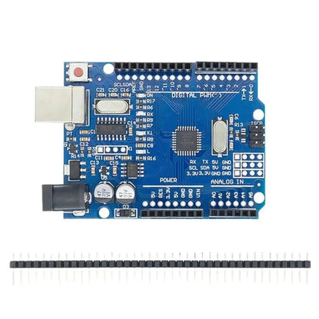
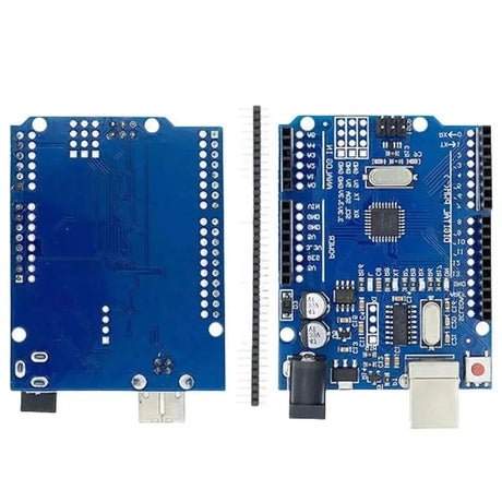
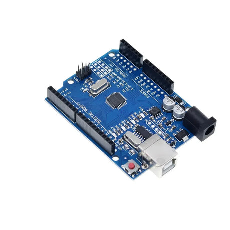
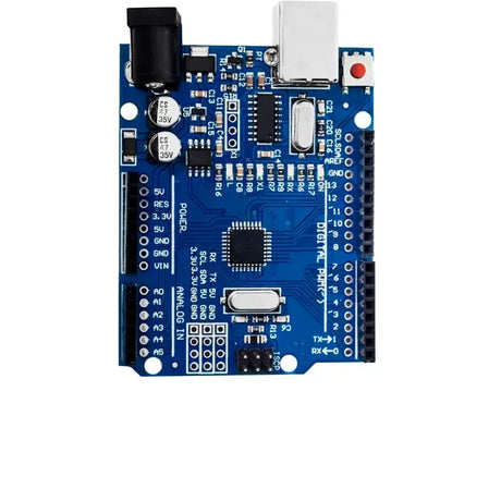
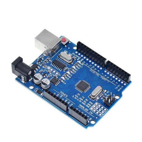
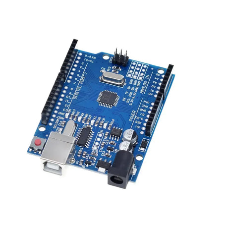
- Arduino uno - ロボットの脳。
- Motor Driver Module (L298N) – To control the motors.
- DC Motors with Wheels - 動きのため。
- シャーシ - すべてのコンポーネントを保持するフレーム。
- Line Sensor Module (e.g., QRE1113) – To detect the line.
- Battery Pack – Power source for the robot.
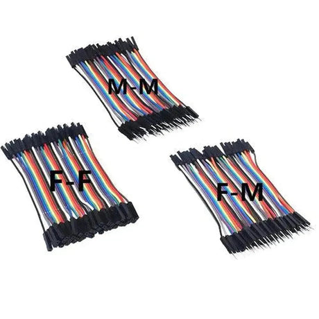
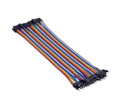
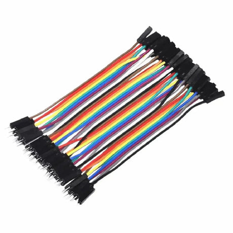
- Jumper Wires – For connections.
- ブレッドボード - 接続のプロトタイピング用。
- ネジ、ナット、ボルト - シャーシを組み立てる。
ステップ1:シャーシの組み立て
シャーシはあなたのロボットの基礎として機能します。 Start by attaching the DC motors to the chassis using screws and nuts. Ensure that the motors are securely fixed to prevent any movement during operation. Attach the wheels to the motor shafts and position the battery pack and Arduino onto the chassis. Make sure all components fit well and are within easy reach for wiring.
Step 2: Wiring the Motors
Connect the DC motors to the motor driver module (L298N).モータードライバーは、ArduinoとMotorsの間のインターフェイスとして機能し、Arduinoが過負荷にならずにモーターの速度と方向を制御できるようにします。
// Connect motor A
const int motorA_EN = 9;
const int motorA_IN1 = 7;
const int motorA_IN2 = 8;

// Connect motor B
const int motorB_EN = 10;
const int motorB_IN3 = 5;
const int motorB_IN4 = 6;

void setup() {
  // Motor A
  pinMode(motorA_EN, OUTPUT);
  pinMode(motorA_IN1, OUTPUT);
  pinMode(motorA_IN2, OUTPUT);

  // Motor B
  pinMode(motorB_EN, OUTPUT);
  pinMode(motorB_IN3, OUTPUT);
  pinMode(motorB_IN4, OUTPUT);
}
Step 3: Connecting the Line Sensor
The line sensor detects the contrast between the line and the surface. Typically, these sensors have infrared LEDs and photodiodes to detect reflecting surfaces. Connect the sensor’s VCC and GND to the Arduino’s 5V and GND respectively. The sensor’s output pins will be connected to the Arduino’s digital or analog pins based on the sensor type.
// Line sensor pins
const int sensorLeft = A0;
const int sensorRight = A1;

void setup() {
  pinMode(sensorLeft, INPUT);
  pinMode(sensorRight, INPUT);
}
Step 4: Writing the Arduino Code
The Arduino code will read the sensor values and control the motors accordingly to follow the line. Below is a simple example of how the code might look:
// Define motor pins
const int motorA_EN = 9;
const int motorA_IN1 = 7;
const int motorA_IN2 = 8;
const int motorB_EN = 10;
const int motorB_IN3 = 5;
const int motorB_IN4 = 6;

// Define sensor pins
const int sensorLeft = A0;
const int sensorRight = A1;

// Threshold for line detection
const int threshold = 500;

void setup() {
  // Initialize motor pins
  pinMode(motorA_EN, OUTPUT);
  pinMode(motorA_IN1, OUTPUT);
  pinMode(motorA_IN2, OUTPUT);

  pinMode(motorB_EN, OUTPUT);
  pinMode(motorB_IN3, OUTPUT);
  pinMode(motorB_IN4, OUTPUT);

  // Initialize sensor pins
  pinMode(sensorLeft, INPUT);
  pinMode(sensorRight, INPUT);

  // Start serial communication for debugging
  Serial.begin(9600);
}

void loop() {
  int leftSensor = analogRead(sensorLeft);
  int rightSensor = analogRead(sensorRight);

  Serial.print("Left: ");
  Serial.print(leftSensor);
  Serial.print(" | Right: ");
  Serial.println(rightSensor);

  if (leftSensor > threshold && rightSensor > threshold) {
    // Move forward
    moveForward();
  }
  else if (leftSensor < threshold && rightSensor > threshold) {
    // Turn right
    turnRight();
  }
  else if (leftSensor > threshold && rightSensor < threshold) {
    // Turn left
    turnLeft();
  }
  else {
    // Stop
    stopMovement();
  }
}

void moveForward() {
  digitalWrite(motorA_IN1, HIGH);
  digitalWrite(motorA_IN2, LOW);
  digitalWrite(motorB_IN3, HIGH);
  digitalWrite(motorB_IN4, LOW);

  analogWrite(motorA_EN, 200);
  analogWrite(motorB_EN, 200);
}

void turnRight() {
  digitalWrite(motorA_IN1, HIGH);
  digitalWrite(motorA_IN2, LOW);
  digitalWrite(motorB_IN3, LOW);
  digitalWrite(motorB_IN4, LOW);

  analogWrite(motorA_EN, 200);
  analogWrite(motorB_EN, 0);
}

void turnLeft() {
  digitalWrite(motorA_IN1, LOW);
  digitalWrite(motorA_IN2, LOW);
  digitalWrite(motorB_IN3, HIGH);
  digitalWrite(motorB_IN4, LOW);

  analogWrite(motorA_EN, 0);
  analogWrite(motorB_EN, 200);
}

void stopMovement() {
  digitalWrite(motorA_IN1, LOW);
  digitalWrite(motorA_IN2, LOW);
  digitalWrite(motorB_IN3, LOW);
  digitalWrite(motorB_IN4, LOW);

  analogWrite(motorA_EN, 0);
  analogWrite(motorB_EN, 0);
}
ステップ5:ロボットのパワーアップ
すべての接続が作成されたら、バッテリーパックをArduinoとモータードライバーに接続します。コンポーネントの損傷を防ぐために極性が正しいことを確認してください。電源を上げる前に、マルチメーターで接続をテストすることをお勧めします。
テストとキャリブレーション
電源を入れた後、ロボットを明確なラインで表面に置きます(たとえば、白い紙に黒いテープ)。 Observe how it behaves and make necessary adjustments.コードのPWM値を変更して最適なパフォーマンスを実現することにより、センサーのしきい値を微調整するか、速度を調整する必要がある場合があります。
成功のためのヒント
- Ensure Stable Connections: ゆるいワイヤーは断続的な動作を引き起こす可能性があります。 Use a breadboard for prototyping and consider soldering connections for a permanent setup.
- 品質センサーを使用してください。 信頼できるラインセンサーは、ロボットのパフォーマンスを大幅に改善できます。
- Calibrate Your Sensors: Different surfaces and lighting conditions can affect sensor readings. Calibrate your thresholds accordingly.
- コードを最適化: Efficient code ensures quick response times. Make sure there are no unnecessary delays in your loop.
Enhancements and Further Learning
基本的なラインフォローロボットの構築に成功したら、機能を強化する機能を追加することを検討してください。
- Intersection Detection: Enable your robot to make decisions at junctions.
- Speed Control: センサー入力に基づいて動的速度調整を実装します。
- ワイヤレスコントロール: Add Bluetooth or Wi-Fi modules to control your robot remotely.
- Obstacle Avoidance: 超音波センサーを取り入れて、障害物の周りをナビゲートします。
Arduinoを使用してラインフォローロボットを構築することは、ロボット工学と組み込みシステムの世界に飛び込む素晴らしい方法です。センサーの統合、モーター制御、リアルタイムの意思決定などの基本的な概念を教えてくれます。 With patience and experimentation, you can expand this basic project into a more complex and capable robot.幸せな建物!