启动机器人项目可能既令人兴奋又具有教育意义,尤其是当您构建像线条跟随机器人之类的有形内容时。利用Arduino是最受欢迎的微控制器之一,即使对于初学者来说,该过程也可以访问。在本指南中,我们将带您浏览步骤,以创建一个可以自动导航路径的简单线条跟随机器人。
您需要的材料
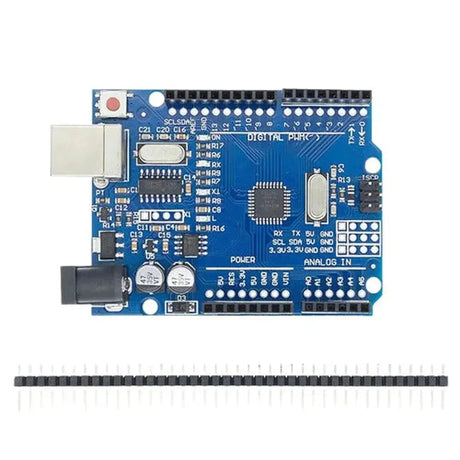
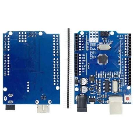
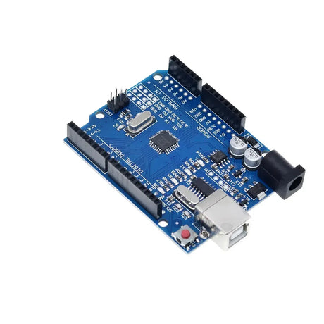
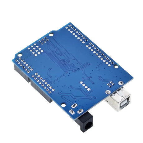
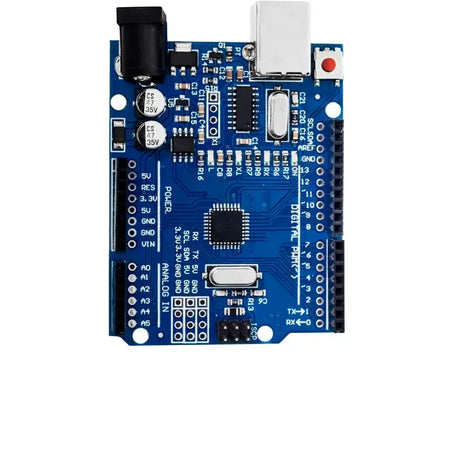
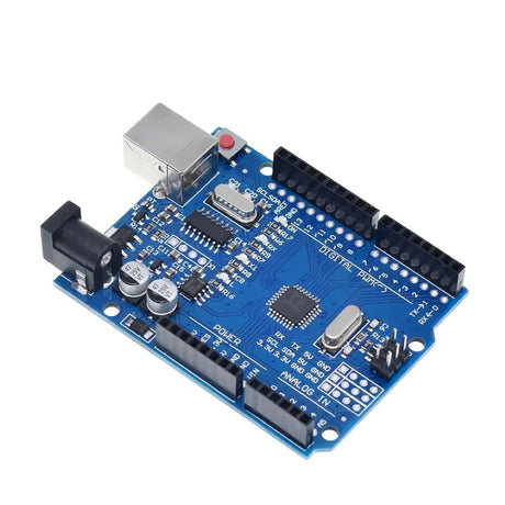
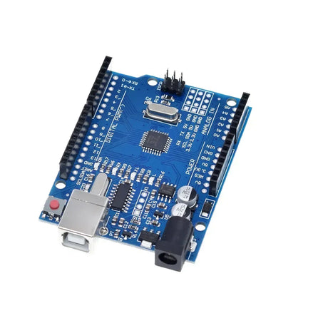
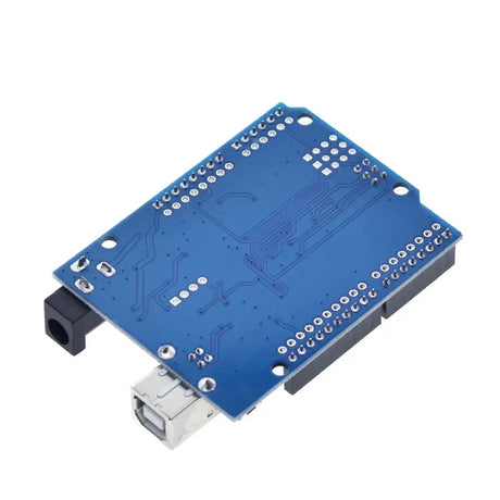
- Arduino Uno - 机器人的大脑。
- 电机驱动器模块(L298N) - 控制电动机。
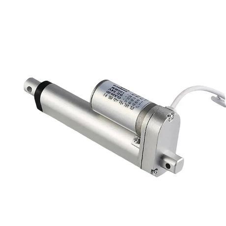
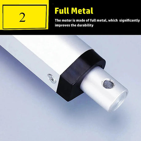
- 带轮的直流电动机 - 移动。
- 机壳 - 容纳所有组件的框架。
- 线传感器模块(例如QRE1113) - 检测线。
- 电池组 - 机器人的电源。
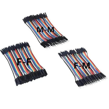
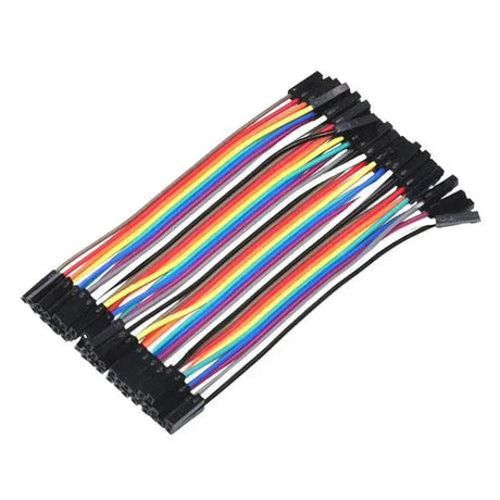
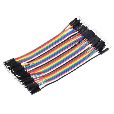
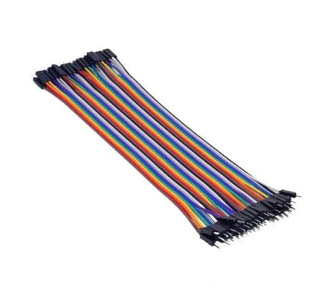
- 跳线 - 连接。
- 面包板 - 用于原型连接。
- 螺丝,螺母和螺栓 - 组装底盘。
步骤1:组装底盘
底盘是您机器人的基础。首先,使用螺钉和螺母将直流电动机连接到机箱。确保电动机牢固固定,以防止操作过程中的任何移动。将车轮连接到电动机轴上,然后将电池组和Arduino放在机箱上。确保所有组件都非常合适,并且可以轻松接触接线。
步骤2:接线电动机
将直流电动机连接到电动机驱动器模块(L298N)。电机驱动器充当Arduino和电动机之间的接口,使Arduino可以控制电动机速度和方向而不会超载。
// Connect motor A
const int motorA_EN = 9;
const int motorA_IN1 = 7;
const int motorA_IN2 = 8;

// Connect motor B
const int motorB_EN = 10;
const int motorB_IN3 = 5;
const int motorB_IN4 = 6;

void setup() {
  // Motor A
  pinMode(motorA_EN, OUTPUT);
  pinMode(motorA_IN1, OUTPUT);
  pinMode(motorA_IN2, OUTPUT);

  // Motor B
  pinMode(motorB_EN, OUTPUT);
  pinMode(motorB_IN3, OUTPUT);
  pinMode(motorB_IN4, OUTPUT);
}
步骤3:连接线路传感器
线传感器检测到线和表面之间的对比度。通常,这些传感器具有红外LED和光二极管,以检测反射表面。将传感器的VCC和GND连接到Arduino的5V和GND。传感器的输出引脚将根据传感器类型连接到Arduino的数字或模拟引脚。
// Line sensor pins
const int sensorLeft = A0;
const int sensorRight = A1;

void setup() {
  pinMode(sensorLeft, INPUT);
  pinMode(sensorRight, INPUT);
}
步骤4:编写Arduino代码
Arduino代码将读取传感器值并相应地控制电动机以遵循该行。以下是代码外观的简单示例:
// Define motor pins
const int motorA_EN = 9;
const int motorA_IN1 = 7;
const int motorA_IN2 = 8;
const int motorB_EN = 10;
const int motorB_IN3 = 5;
const int motorB_IN4 = 6;

// Define sensor pins
const int sensorLeft = A0;
const int sensorRight = A1;

// Threshold for line detection
const int threshold = 500;

void setup() {
  // Initialize motor pins
  pinMode(motorA_EN, OUTPUT);
  pinMode(motorA_IN1, OUTPUT);
  pinMode(motorA_IN2, OUTPUT);

  pinMode(motorB_EN, OUTPUT);
  pinMode(motorB_IN3, OUTPUT);
  pinMode(motorB_IN4, OUTPUT);

  // Initialize sensor pins
  pinMode(sensorLeft, INPUT);
  pinMode(sensorRight, INPUT);

  // Start serial communication for debugging
  Serial.begin(9600);
}

void loop() {
  int leftSensor = analogRead(sensorLeft);
  int rightSensor = analogRead(sensorRight);

  Serial.print("Left: ");
  Serial.print(leftSensor);
  Serial.print(" | Right: ");
  Serial.println(rightSensor);

  if (leftSensor > threshold && rightSensor > threshold) {
    // Move forward
    moveForward();
  }
  else if (leftSensor < threshold && rightSensor > threshold) {
    // Turn right
    turnRight();
  }
  else if (leftSensor > threshold && rightSensor < threshold) {
    // Turn left
    turnLeft();
  }
  else {
    // Stop
    stopMovement();
  }
}

void moveForward() {
  digitalWrite(motorA_IN1, HIGH);
  digitalWrite(motorA_IN2, LOW);
  digitalWrite(motorB_IN3, HIGH);
  digitalWrite(motorB_IN4, LOW);

  analogWrite(motorA_EN, 200);
  analogWrite(motorB_EN, 200);
}

void turnRight() {
  digitalWrite(motorA_IN1, HIGH);
  digitalWrite(motorA_IN2, LOW);
  digitalWrite(motorB_IN3, LOW);
  digitalWrite(motorB_IN4, LOW);

  analogWrite(motorA_EN, 200);
  analogWrite(motorB_EN, 0);
}

void turnLeft() {
  digitalWrite(motorA_IN1, LOW);
  digitalWrite(motorA_IN2, LOW);
  digitalWrite(motorB_IN3, HIGH);
  digitalWrite(motorB_IN4, LOW);

  analogWrite(motorA_EN, 0);
  analogWrite(motorB_EN, 200);
}

void stopMovement() {
  digitalWrite(motorA_IN1, LOW);
  digitalWrite(motorA_IN2, LOW);
  digitalWrite(motorB_IN3, LOW);
  digitalWrite(motorB_IN4, LOW);

  analogWrite(motorA_EN, 0);
  analogWrite(motorB_EN, 0);
}
步骤5:为机器人供电
建立所有连接后,将电池组连接到Arduino和电机驱动器。确保极性是正确的,以防止对组件的任何损害。在供电之前测试与万用表的连接是一种很好的做法。
测试和校准
电源后,将机器人放在带有透明线条的表面上(例如,黑色胶带在白纸上)。观察其行为方式并进行必要的调整。您可能需要调整传感器阈值或通过更改代码中的PWM值以实现最佳性能来调整速度。
成功的提示
- 确保稳定的连接: 松动的电线会导致间歇性行为。使用面包板进行原型制作,并考虑为永久设置焊接连接。
- 使用质量传感器: 可靠的线路传感器可以显着改善机器人的性能。
- 校准传感器: 不同的表面和照明条件会影响传感器读数。相应地校准阈值。
- 优化代码: 有效的代码可确保快速响应时间。确保循环中没有不必要的延迟。
增强和进一步学习
成功构建了一个基本的线条遵循机器人后,请考虑添加更多功能以增强其功能:
- 交叉检测: 使您的机器人能够在交界处做出决定。
- 速度控制: 根据传感器输入实现动态速度调整。
- 无线控制: 添加蓝牙或Wi-Fi模块以远程控制您的机器人。
- 避免障碍: 合并超声波传感器以在障碍物周围导航。
使用Arduino建立遵循线条的机器人是潜入机器人和嵌入式系统世界的绝佳方式。它教您基本概念,例如传感器集成,电动机控制和实时决策。借助耐心和实验,您可以将这个基本项目扩展到更复杂,更有能力的机器人。快乐的建筑!